I came back to the 1806 olduino after a break and encountered a bug that has me scratching my head. I’m using something I call the fakeloader to emulate 1802 load mode on the 1806. fakeloader.c gets compiled to low memory and looks to the AVR external loader like an 1802’s load mode. Fakeloader loads the code from the external loader to location 0x800 and runs it from there. The AVR external loader does actually know what’s going on, If it sees code compiled for location 0 it puts the 1802 in load mode as usual; if it sees code compiled for a different address it puts the processor in RUN and counts on the fakeloader.
I had a little test program called hellofromtheotherside.c that i would run that could report where it was loaded and what kind of processor it was compiled for. The trouble was it didn’t work! I could run almost anything compiling it for location 0x800 and loading it via the fakeloader but not hellofromtheotherside. After much dinking around my simplest fail/no-fail case involves code that is never executed! The test case is below, In the function dump(which is never executed!) there’s a for loop. I can make it fail or run depending on whether there are a couple of print statements inside the for loop or not. Although the code is never executed, the version with the print statements inside the loop compiles to more code and ALTHOUGH THAT CODE IS NEVER EXECUTED it seems to load to low memory being overwritten as well as simply not printing. The version below is the one that fails. If I were to close out the for loop on the 12th(**A) line and comment out the } on the 15th line(**B) it would work.
Obviously, everything after dump() including main() and the library routines are in slightly different locations but I don’t know what’s leading to the failure. cr*p.
void fun(int i){}
int bar(int s,int b,int c){
	int local=42;
	return local+c;
}
#include <nstdlib.h>
#include <cpu1802spd4port7.h>
#define putc(x) out(7,x)
void dump(unsigned char* data, unsigned int len){
	unsigned int i=0;
	printf("dumping %d bytes at %x",len,data);
	for(i=0;i<len;i++){//}//**A
		if (0==(i%8)) printf("\n%x ",data);
		printf("%cx ",*data++);
	}//**B
	printf("\n");
}
void main()
{
	char* dummy=(void*) &fun;
	printf("Hello World!9!\n");
}
#include <nstdlib.c>
UPDATE:
The failing case, with the printfs outside the loop body generates LESS code than the working case(because the compiler puts i in a register). I stuck enough db’s in the bottom of dump to move main to the same place and it suddenly works! Moving them down to above the nstdlib include also works. Moving them down to below the nstdlib include also works. So something in the epilog is getting b*ggered.
Further diddling by taking out filler I can get it to work with 2 bytes of filler or fail with 1. In the guts of the epilog it works with lcc1802init: at 15EC and fails when it’s at 15E8. In any case, by the time it gets to the call routine it will be the same because there’s an align 256 that brings it to 0x1700 in either case. I give up for now.
Also, I’ve been assuming this won’t fail in the emulator but don’t really know that. worth a try tomorrow.
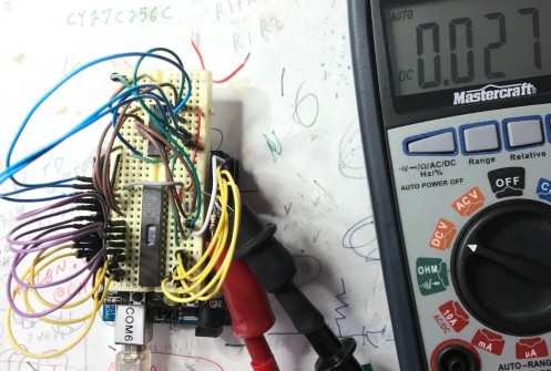
I was able to get the breadboard programmer to read(I think) the CY27C256 EPROMS but my attempts at programming failed. The essence of the programming is to apply a series of 200 uS low pulses on the chip select (pin 20) while holding VPP(pin 1) at 12 volts. I first built that into the ghetto programmer code but when it didn’t work I just made a standalone sketch that would do 30 pulses and changed all the other signal levels with jumpers. I set it up with A14,13 & 12 at +V and the others at 0 so i would be programming location 7000; i pulled D0-D7 high, held /OE(pin 22) at +V; applied 12V from a wall wart to VPP, and pulsed pin 22. After 30 pulses I disconnected the jumpers and tried to read the same location but all the bits remain stubbornly 0.
I tried each of two chips with the same result so it’s more likely some error on my part than a faulty part.
The chips have a signature built in which you read out by holding all address lines low except A9 which you connect to 12V(!). I was able to do that on the breadboard and read out the signature successfully so it’s even less likely that the chips are bad. I have a friend in Toronto who can maybe program them for me so i’ll try that. I was surprised not to have found an arduino shield or schematic for programming them but i see why now – it’s a lot of trouble.
The pics below show the eprom on the breadboard set up to read the signature and then to program it. In each case the 12V VPP is being supplied from a wall wart through the alligator clips at the bottom. There’s an arduino off to the right supplying 5V and, in the programming case, pulsing the /CE pin low.


http://www.armory.com/~rstevew/Public/Pgmrs/EPROM/AndrewMcCubbin/howto.txt
The Cypress CY27C256T is a UV erasable EPROM. Mostly those are the wide .6″ DIP’s but this is available in a .3″ wide package which means it will fit under the non-volatile RAM on the membership card. That spot is meant for a RAM but the pinouts are similar enough that I should be able to make it work for at least the bottom part of the address space. To program it I’m adapting my ghetto eeprom programmer which I last used for the Boyd Calculator reprogramming. I don’t want to bollix it permanently so I’m trying to be careful with the changes. The first try is a read test. For this all I had to do was connect pin 1(VPP) to +V along with pins 27(MA14) and 26(MA13), pin 23(MA11) goes to A11. Probably if I were smarter I’d make an adapter socket to match up with the footprint for the AT28C64 that the programmer was originally made for. For now, I’ll just have to be careful.
 I fired it up and it does read as 0’s which is good. I was also able to measure the 5V current at 27MA(including the 74595) and, by switching the /CE to +V, put the chip in low power mode and see the current drop to 7MA. The 74HC595’s data sheet says the supply current is max .08MA so I’ll ignore that!
To actually program it I have to set VPP(pin 1) to 12V with /OE and /CE held high then pulse /CE low many times for 200us at a time until the programming takes. Then do it twice as many times again. Fortunately the VPP is static at 12V so if i can figure out how to source it I don’t have to pulse it. The ghetto programmer doesn’t normally control /CE but there’s no /WE required so that signal is freed up to use(the arduino’s D2).
Below is stuff I’m gathering for the programming push:
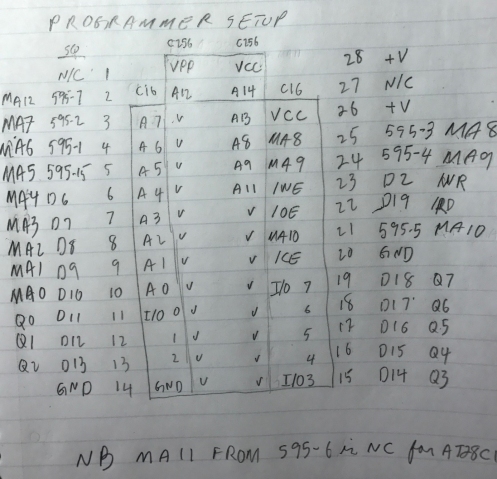
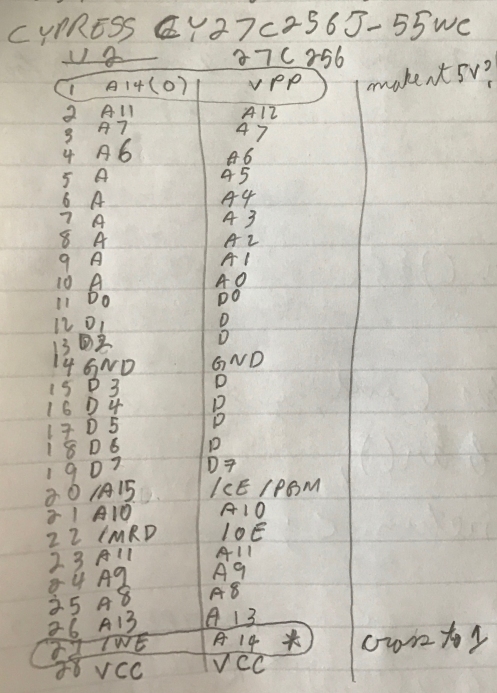
As regards putting the EPROM chip into the Membership card, I have to think about pins 1,20, and 27. As currently routed, pin 1(VPP) will fluctuate with A14 which theoretically is ok. pin 20(/CE) needs to be wired to some variant of A15 to divide the address space with the RAM and pin 27(A14) would fluctuate with /WE which again theoretically doesn’t matter for testing since I won’t write in the ROM. So, hell, I may just be able to leave it all alone except for whatever jumpers lee provides for addressing. Aaand it looks like the default jumpers on the board address the ROM high and the RAM low. Perfect for my first programming attempt. I’ll write something in the high part of the chip and then see if i can read it with the 1802.
Programming Instructions for the CY27C256
UPDATE: Poking around my pile of castoffs I have a 12V wall wart that actually delivers just a bit over 12V. I may try to get a regulator tomorrow or i may just try it out.
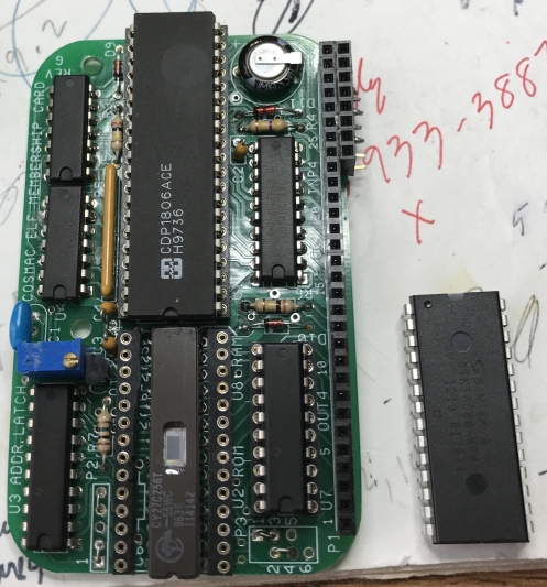
Below is the EPROM in place under the RAM. I actually have to solder in some pin sockets and a capacitor before i run it but the fit looks fine.
Xmodem is a very simple and easy to understand protocol but i have spent a LOT of time diddling with it. I’m trying to combine it with some bit bang serial routines for the 1802 as a return to a serial bootloader. I’m really just using xmodem for pacing and i’m not checking any error conditions. Testing it involved my usual “fantastic collection of stamps” approach with a python sender on windows, a couple of serial ports, and the logic analyzer.
After hours of flaky results it finally started working today when I overwrote low memory and had to switch back from the 1806 to the 1802. Now it seems bulletproof! I’ll retry with the 1806 tomorrow with some confidence that i can make it work.
The reason for the custom python sender is so i could build up from working with very small blocks and visible control characters. I’m munging all the code together here so i can track where i was when it started working.
#include <olduino.h>
#include <nstdlib.h>
#include <cpu1802spd4port7.h>
int XR(unsigned char *);
void dump(unsigned char* data, unsigned int len){
	unsigned int i=0;
	printf("dumping %d bytes at %x",len,data);
	for(i=0;i<len;i++){
		if (0==(i%8)) printf("\n%x ",data);
		printf("%cx ",*data++);
	}
	printf("\n");
}
void main(){
	int ret;
	asm(" seq\n"); //make sure Q is high to start
	ret=XR((unsigned char *)0x7000);
	printf("XR returns %x\n",ret);
	dump((unsigned char *)0x7000,ret-0x7000-1);
	while(1);
}
void includeser(){
	asm(" include xrwjr2.asm");
}
#include <olduino.c>
#include <nstdlib.c>
**************xrwjr2,asm include file follows ***************
NAK:	EQU 0x15;'N'
SOH:	EQU 0x01;'S'
EOT:	EQU 0x04;'T'
ACK:	EQU 0x06;'K'
Rrcv:	EQU 8
Rsnd:	EQU 9
blksize:	EQU 128
trc:	MACRO
	dec 2
	str 2
	out 7
	ENDM
; XMODEM receiver based on xr.asm by Michael H Riley and serial routines by Josh Bensadon
; See bottom of file for full acknowledgements and links.
; On entry R12 points to memory where received data will go
; On exit R15 has the last byte written
	align 64
_XR:	   ldaD	   Rsnd,serout
	   ldaD    Rrcv,serin
	ldi '<' 	trc  	   ldi     NAK                 ; need to send NAK to start            sep     Rsnd filelp:    ;receive address is in R12, length goes in R11 ;begining of block read. returns to filelp or exits to filedn   				            sep     Rrcv               ; wait for next incoming character            smi     EOT              ; check for EOT            lbz     filedn           ; jump if so 	   sep     Rrcv               ; read block number            sep     Rrcv               ; read inverted block number            ldi     blksize             ; 128 bytes to receive            plo     r11 readlp:    sep     Rrcv               ; read data byte            str     r12                  ; store into output buffer            inc     r12                  ; point to next position            dec     r11                  ; decrement block count            glo     r11                  ; see if done            bnz     readlp              ; loop back if not ;end of block read            sep     Rrcv               ; read checksum byte            ldi     ACK                  ; send an ACK            sep     Rsnd            lbr     filelp              ; loop back for more filedn:                ldi     ACK                  ; acknowledge end of transmission            sep     Rsnd 	   glo	   R12			;copy last address to return register 	   plo     R15 	   ghi     R12 	   phi     R15 	ldi '>'
	trc
           cretn	           	; and return to caller

; *******************************************************************
; *** This software is copyright 2005 by Michael H Riley          ***
; *** You have permission to use, modify, copy, and distribute    ***
; *** this software so long as this copyright notice is retained. ***
; *** This software may not be used in commercial applications    ***
; *** without express written permission from the author.         ***
; *******************************************************************
;**********************************************************************
;bit-bang Serial routines adapted from Josh Bensadon's VELFbios-v3.1.asm
;Transmit Byte via Q connected to RS232 driver
;call via SCRT
;Byte to send in D
;Destroys r14
;----------------------------------------------------------------------
 	IFNDEF 	LCC1802CPUSPEED
LCC1802CPUSPEED EQU 4000000
 	ENDIF
bitdelay: MACRO baudrate,cpuspeed,baseline,xreg
	rept ((cpuspeed/(baudrate*8)-baseline))/3
	NOP
	endm
	rept (((cpuspeed/(baudrate*8)-baseline)#3))>=1
	sex xreg
	endm
	ENDM
__BAUDRATE EQU 	9600
	align 32
serout:			;entry from assembly with char in D
	phi R14		;save char in R14.1
	ldi 9		;9 bits to transmit (1 start + 8 data)
	plo r14
	ghi R14
	shl		;set start bit
	rshr		;DF=0

.txcloop:
	bdf $+5		;10.5   jump to seq to send a 1 bit
	req		;11.5   send a 0 bit
	br $+5		;1      jump +5 to next shift
	seq		;11.5   send a 1 bit
	br $+2		;1      jump +2 to next shift (NOP for timing)
	rshr		;2      shift next bit to DF flag
	phi r14		;3      save D in r14.1
	DEC r14		;4      dec bit count
	glo r14		;5      get bit count
	bz .txcret	;6      if 0 then all 9 bits (start and data) sent
	ghi r14		;7      restore D
	bitdelay __BAUDRATE,LCC1802CPUSPEED,20,2
	br .txcloop	;9.5    loop back to send next bit
.txcret: ghi r14		;7
	bitdelay __BAUDRATE,LCC1802CPUSPEED,16,2
	seq		;11.5 stop bit
	bitdelay __BAUDRATE,LCC1802CPUSPEED,4,2
	sep R3		;return
	br serout	;reset for next time
;**********************************************************************
;rx_char
;Receive Byte via EF2 connected to RS232 receiver
;Receives 8 bits
;call via sep
;Returns with Byte received in D
;Destroys r14.0
;----------------------------------------------------------------------
	align 32
serin:
 	ldi 8		;start bit +7 bits from loop, last bit on returning
	plo r14
	ldi 0
.rxcw:			;wait for start bit
	bn3 .rxcw	;each instr takes 9us, we need 104us = 11.5
			;delay 1/2 bit time to center samples
	NOP		;     Don't test for correct start bit
	NOP		;     it will work. if there's too much
	NOP		;     noise on the line, shorten the cable!
.rxcloop:
	bitdelay __BAUDRATE,LCC1802CPUSPEED,20,2
	b3 $+6		;11.5 sample rx input bit
	ori 80h		;1
	br $+4		;2
	phi r14		;1
	phi r14		;2
	shr		;3
	phi r14		;4
	DEC r14		;5
	glo r14		;6
	bz .rxcret	;7
	ghi r14		;8
	br  .rxcloop	;9
.rxcret: ghi r14	;8
	ghi r14		;9
	bitdelay __BAUDRATE,LCC1802CPUSPEED,20,2
	b3 $+4		;11.5 sample last rx input bit
	ori 80h		; for a 1 bit
	sep R3		;return
	br  serin	;for next time

_putcser:
	ldad Rsnd,serout
	glo R12
	sep Rsnd
	cretn

_getcser:
	ldad Rrcv,serin
	sep Rrcv
	plo R15
	ldi 0
	phi R15
	cretn

************************SSX3.PY custom sender follows *****************
from __future__ import print_function
import sys
import logging
logging.basicConfig()
import serial
try:
    from cStringIO import StringIO
except:
    from StringIO import StringIO
from time import sleep
import os
if len(sys.argv)>1:
    filename=sys.argv[1]
else:
    filename="xserial.c"
fileSize=os.path.getsize(filename)
print ("File Size is",fileSize)

def xmodem_send(serial, file):
	NAK='\x15'
	blocksize=128
	t=0
	#	t, anim ='|/-\\'
	while 1:
	    if serial.read(1) != NAK:
		t = t + 1
		print ('.')
		if t == 3 : return False
	    else:
		break

	p = 1
	s = file.read(blocksize)
	while s:
	    s = s + '\xFF'*(blocksize - len(s))
	    chk = 0
	    for c in s:
		chk+=ord(c)
		#print (c,ord(c),chk,chk%256)
	    while 1:
		serial.write('\x01')#('S') #SOH)
		print('S')
		serial.write(chr(p))
		print('n')
		serial.write(chr(255 - p))
		print('-')
		serial.write(s)
		print(s)
		serial.write(chr(chk%256))
		#serial.write('ZZZZZZZZZZZZZZZZZZZZZZZZZZZZZZZZZZZZZZZZZZZZZZZZZZZZZZZZZZZZZZZZZZZZZZZZZZZZZZZZZZZZZZZZZZZZZZ')
		print('c')
		serial.flush()
		print ('checksum is ',format(chk%256, '02X'),end=' ')
		answer = serial.read(1)
		if len(answer)!=0:
			print('answer is ',format(ord(answer[0]), '02X'))
		else:
			print ("Timeout I guess")
		if  answer == '\x15': continue
		if  answer == '\x06': break
		return False
	    s = file.read(blocksize)
	    p = (p + 1)%256
	    print ('.')
	serial.write('\x04')#('T')
	serial.flush()
	sleep(.1)
	serial.write('TTTTTTTTTTTTTTTTTTTTTTTTTTTTTTTTTTTTTTTTTTTTTTTT')
	serial.flush()

	return True

#Main program starts here - define the serial port, set RTS off, then open it
#open the file to be loaded
stream = open(filename,'rb')

port = serial.Serial(parity=serial.PARITY_NONE,
                     bytesize=serial.EIGHTBITS,
                     stopbits=serial.STOPBITS_ONE,timeout=10,xonxoff=0,
                     rtscts=0,dsrdtr=0,baudrate=9600)
port.rts=False
port.port='COM4'
port.open()
port.rts=True
sleep(0.001)
port.rts=False
port.flushInput()
#transfer the file
result=xmodem_send(port, stream)

stream.close()
port.close()

if result:
    print ("\ntransfer successful")
    sleep(.25)
else:
    print ("\ntransfer unsuccessful")
    #x=raw_input("press enter to continue...");
I always want the last word so that wordpress doesn’t eat my code!
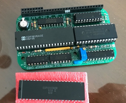
A few weeks ago one of the fellows on the Cosmac Elf mailing list spotted some surplus calculators based on the CDP1805 processor chip. This is a follow-on to the 1802 with a few extra instructions and a 64 byte onboard ram. Much discussion ensued and many of us bought the calculators for novelty value or to hack. I, of course, set out to re-program mine in C with the idea of implementing a “little language” that would output some sort of ascii art or patterns on the printer.
The baseline calculator dates from the eighties and was made as a contractors tool for doing math with feet, inches, and sixteenths.


It’s very well made: all through-hole parts with no fewer than three processors. The 1805 does the actual calculations and there’s a seiko and an 80c49 that are dedicated to the printer. Opening it up we see a main PCB that has the 1805 logic and a 4K 2532 eprom. On top of that is a daughter board with the printer and display. The display uses a 7218B display driver that can be jumpered to display decimal digits plus a few characters or to display hex 0-F. Everything is nicely done with good quality connectors and screws for assembly.
Josh Bensadon on the mailing list went at the 1805 code with a will and produced a beautifully commented disassembly showing how the display, keyboard, and printer worked. The code is not concise but it’s pretty easy to follow (thanks Josh!).
I’ve replaced the 4K EPROM with a 2K flash EEPROM which is faster and easier for me to program. I re-jumpered the display chip to display hex instead of decimal. This gives up the ability to display blanks but it seemed worth it for hacking. To program it, I’m working in C to produce a hex file. That gets converted to a C header file for an arduino program that writes the EEPROM which I then move over into the calculator. It’s a bit outlandish but it works.
The code is standard LCC1802 but I have jiggered the epilog code to leave out the math routines. That keeps things pretty easily within the 2K EEPROM space. At first, when i was just displaying memory, working in C seemed painful but when i started implementing my “little language” it felt much better. So far the “language” is all two byte instructions:
- 00 xx is display the memory at location 10xx (that’s where the 64 byte ram is located)
- 01 xx is increment the memory location
- 02 xx is goto
- 03 nn is delay nn*4 ms
- 04 xx is display the bottom byte of the stack pointer(xx is ignored)
The monitor just implements the basic functions:
- display memory, moving backward and forward with + and – keys
- switch between the eeprom memory at 0 and the 64 byte onboard RAM at 0x1000 with the REM key
- Change memory by pressing MS and two hex keys
- Begin interpreting the program at the location counter by pressing the X key (times)
The 04xx instruction displays 20 meaning that the stack has used up 32 of 64 bytes leaving 32 for the “little language” program. I haven’t tried but i would think I could improve that. For example main() gets entered by subroutine call and saves 4 registers but it’s never going to return or restore them. Execute() similarly saves 4 registers so if i had to move that inline in main()I’d have 16 bytes free right there.
Looking at the compiled program It uses the EEPROM up to 0x5B6 leaving another 500-600 bytes for “little language” features. After all – I have a total of 2,112 bytes of memory. Surely that ought to be enough for anybody!
Here’s the working version of the monitor/interpreter and one assembly include where I adapted some of josh’s disassembly of the original code. The keyboard is conceptually a matrix of 7X4 keys. A row of keys is activated by doing an OUT to port 1,2,3,4,5 or 6 or by setting Q and pressing a single key will assert one of EF1 to 4.
 #include "olduino.h"
#define initleds() 	asm(" req\n seq\n dec 2\n out 7\n req\n")
unsigned char boydscan();
void boydinc(){
	asm(" include \"boydscan.inc\"\n");
}
void disp1(unsigned char d){//display a byte as two hex digits
	asm(" glo 12\n ani 0x0f\n" //prep bottom digit
		" dec 2\n str 2\n out 7\n"
		" glo 12\n shr\n shr\n shr\n shr\n" //prep top digit
		" dec 2\n str 2\n out 7\n"
		);

}

void dispmemloc(unsigned char * loc){
	register unsigned int lint;
	initleds();
	disp1(*(loc+1));
	disp1(*loc);
	lint=(unsigned int)loc;
	disp1((unsigned int)loc&0xff);
	disp1(lint>>8);
}
void dispval(unsigned char v){
	register unsigned int i;
	initleds();
	disp1(v);
	for (i=6;i!=0;i--) out(7,0);

}
unsigned int getsp(){//return stack pointer value
	asm(" cpy2 r15,sp\n"  	//copy stack pointer to return reg
		" cretn\n");		//return it to the caller;
	return 0;				//not executed
}
unsigned char * execute(unsigned char * loc){
	unsigned char op,val;
	unsigned char * mp;
	while(1){
		op=*loc; val=*(loc+1);
		switch (op){
			case 0: //display memory at mem[val];
				mp=(unsigned char *)(4096+val);
				dispval(*mp); delay(1000);
				break;
			case 1: //increment location val
				mp=(unsigned char *)(4096+val);
				*mp+=1;
				break;
			case 2: //goto val
				loc=(unsigned char *)(val+4096-2); //ugh
				break;
			case 3: //delay val*4 ms
				delay(val*4);
				break;
			case 4: //display stack pointer;
				dispval(getsp());
				delay(250);
				break;
			default:
				dispval(0x41); delay(250);
				dispmemloc(loc); delay(5000);
				break;
		}
		loc+=2;
	}
	return loc;
}

void main()
{
	unsigned char * loc=0;
	unsigned char memtype='o'; //displaying o=eeprom,a=ram
	unsigned char k,k2;
	dispval(0x42);
	delay(1000);
	while(1){
		dispmemloc(loc);
		k=boydscan();
		switch(k){
			case 16: //+
				loc +=1;
				break;
			case 17: //-
				loc -=1;
				break;
			case 18:	//rem
				if (memtype=='o'){
					loc=(unsigned char *)4096;
					memtype='a';
				}else{
					loc=(unsigned char *)0;
					memtype='o';
				}
				break;
			case 19: //ms
				dispmemloc(loc); //makes a blink
				k=boydscan(); dispval(k); delay(250);
				k2=boydscan(); dispval(k2); delay(250);
				*loc=(k<<4)+k2;
				break;
			case 20: //X for execute
				dispval(0x45);
				delay(250);
				loc=execute(loc);
				break;
			default:
				dispval(k);
				delay(250);
		}
	}
}

#include "olduino.c" //for the delay routine
_boydscan:			;SCAN THE KEYBOARD
		sex	r14 	;set up "don't care" X register
		rldi	r15,0	; r15 is return value
.scan:		OUT	1                     ;109: 61
		B1	.KEY_12                     ;10A: 34 50
		B2	.KEY_8                      ;10C: 35 60
		B3	.KEY_4                      ;10E: 36 70
		B4	.KEY_0                      ;110: 37 80
		OUT	2                     ;112: 62
		B1	.KEY_13                     ;113: 34 54
		B2	.KEY_9                      ;115: 35 64
		B3	.KEY_5                      ;117: 36 74
		B4	.KEY_1                      ;119: 37 84
		OUT	3                     ;11B: 63
		B1	.KEY_14                     ;11C: 34 58
		B2	.KEY_10                     ;11E: 35 68
		B3	.KEY_6                      ;120: 36 78
		B4	.KEY_2                      ;122: 37 88
		OUT	4                     ;124: 64
		B1	.KEY_15                     ;125: 34 5C
		B2	.KEY_11                     ;127: 35 6C
		B3	.KEY_7                      ;129: 36 7C
		B4	.KEY_3                      ;12B: 37 8C
		OUT	5                     ;12D: 65
		B1	.KEY_DIV_WHOLE              ;12E: 34 99
		B2	.KEY_MUL                    ;130: 35 96
		B3	.KEY_SUB                    ;132: 36 93
		B4	.KEY_ADD                    ;134: 37 90
		OUT	6                     ;136: 66
		B1	.KEY_REM                    ;137: 34 A5
		B2	.KEY_MEM_STORE              ;139: 35 A2
		B3	.KEY_MEM_RECALL             ;13B: 36 9F
		B4	.KEY_EQU                    ;13D: 37 9C
		SEQ                                ;13F: 7B
		B1	.KEY_DIV_FIS                ;140: 34 B1
		B2	.KEY_CLEAR                  ;142: 35 AE
		B3	.KEY_CLR_ENTRY              ;144: 36 AB
		B4	.KEY_INV_SIGN               ;146: 37 A8
		REQ                                ;148: 7A
;here we have no keys pressed, if r15.0 has a value, return it -1
		glo	r15
		bz	.scan
		dec	r15
		sex	r2	;restore the X register before returning
		cretn

.KEY_12		LDI	13                         ;150: F8  C
		BR	.KEY_SAVE                   ;152: 30 B4
.KEY_13		LDI	14                         ;154: F8  D
		BR	.KEY_SAVE                   ;156: 30 B4
.KEY_14		LDI	15                         ;158: F8  E
		BR	.KEY_SAVE                   ;15A: 30 B4
.KEY_15		LDI	16                         ;15C: F8  F
		BR	.KEY_SAVE                   ;15E: 30 B4
.KEY_8		LDI	 9                         ;160: F8  8
		BR	.KEY_SAVE                   ;162: 30 B4
.KEY_9		LDI	 10                         ;164: F8  9
		BR	.KEY_SAVE                   ;166: 30 B4
.KEY_10		LDI	11                         ;168: F8  A
		BR	.KEY_SAVE                   ;16A: 30 B4
.KEY_11		LDI	12                         ;16C: F8  B
		BR	.KEY_SAVE                   ;16E: 30 B4
.KEY_4		LDI	 5                         ;170: F8  4
		BR	.KEY_SAVE                   ;172: 30 B4
.KEY_5		LDI	 6                         ;174: F8  5
		BR	.KEY_SAVE                   ;176: 30 B4
.KEY_6		LDI	 7                         ;178: F8  6
		BR	.KEY_SAVE                   ;17A: 30 B4
.KEY_7		LDI	 8                         ;17C: F8  7
		BR	.KEY_SAVE                   ;17E: 30 B4
.KEY_0		LDI	 1                         ;180: F8  0
		BR	.KEY_SAVE                   ;182: 30 B4
.KEY_1		LDI	 2                         ;184: F8  1
		BR	.KEY_SAVE                   ;186: 30 B4
.KEY_2		LDI	 3                         ;188: F8  2
		BR	.KEY_SAVE                   ;18A: 30 B4
.KEY_3		LDI	 4                         ;18C: F8  3
		BR	.KEY_SAVE                   ;18E: 30 B4

.KEY_ADD	ldi	16+1
		br	.key_save
.KEY_SUB:	ldi	17+1
		br	.key_save
.KEY_MUL:	ldi	20+1
		br	.key_save
.KEY_MEM_STORE:	ldi	19+1
		br	.key_save

.KEY_REM:	ldi	18+1
		br	.key_save
.KEY_CLEAR:	req
		ldi	20+1
		br	.key_save
.KEY_INV_SIGN:	req
.KEY_CLR_ENTRY:	req
.KEY_DIV_FIS:	req
.KEY_EQU:
.KEY_DIV_WHOLE:
.KEY_MEM_RECALL:
.KEY_SAVE:	plo 15
		br .scan
Below is a video of the hoops I’ve been jumping through to load code into the calculator
And here’s the calculator baseline function:
LCC1802 has a simple form of inline assembly: if you code asm(“foo”); you get “foo” directly emitted in the assembly output from the compiler. This is fine for the simplest cases (seq,req etc.) but it would be nice to be able to access local variables. I found a more advanced version of the assembly patch i used which seems to be meant to do exactly that. http://www.yqcomputer.com/234_714_1.htm
This is from more than a decade ago but LCC itself is much older than that so that’s ok. I worked it into my working copy but the results so far are not encouraging:
The fragment below shows the C code and the resulting assembly code. The asm calls are just to get the substitutions for the variable names for a global:g, two parameters: p1 and p2, and two locals: L1,L2. The global g generates _g which is fine but i knew that! the locals L1 and L2 generate -4 and -6 instead of something like 2 and 0 or register references. The parameters generate 0 and 2 instead of (I would have hoped) referring to the registers or, worst case, offsets of 6 and 8 from the stack pointer. I may poke at this again and it may just be a matter of adding the frame size(which is actually 6) but in the end i question whether it’s worth it.
int g=7;
void turnqoff(int p1,int p2){
	int L1,L2;
	L1=42; L2=43;
	asm(";	L1:$L1)\n");
	asm(";	L2:$L2\n");
	asm(";	g:$g\n");
	asm(";	p1:$p1 p2:$p2\n");
}
*************compiled code follows**************
_g:
	dw 7
_turnqoff:		;framesize=6
	reserve 4
	st2 R12,'O',sp,(6+1)
	inc memaddr
	str2 R13,memaddr
;void turnqoff(int p1,int p2){
;	L1=42; L2=43;
	st2I 42,'O',sp,(2+1); ASGNI2(addr,acon)
	st2I 43,'O',sp,(0+1); ASGNI2(addr,acon)
;	asm(";	L1:$L1)\n");
;	L1:-4)
;	asm(";	L2:$L2\n");
;	L2:-6
;	asm(";	g:$g\n");
;	g:_g
;	asm(";	p1:$p1 p2:$p2\n");
;	p1:0 p2:2
The 1804/5/6 have a built-in 8 bit timer/counter with a bunch of functions. In timer mode, it decrements automatically every 32 machine cycles. When it gets to 0 it resets to whatever you first set it to and counts down again. It can cause an interrupt at 0 OR, it can just toggle Q. This generates a constant square wave without any further program interference. The range, on my 4MHZ olduino is about 30HZ to 7.8KHZ. If you can set the chip up with a ROM or some other way of feeding it instructions it’s an easy way to make sure you have a genuine 1804/5/6. The 10 byte program below generates a 30HZ square wave on my 4MHZ 1806.
68 0D CID ; disable timer interrupts
F8 FF LDI 255; maximum value
68 06 LDC ;load the timer
68 09 ETQ ; enable the Q toggle
68 07 STM ; start the timer
For extra points, it occurred to me that you could use this to make music in the traditional square wave sense. I wrote a tone(frequency,duration) function that calculates the initial timer value needed and starts the timer toggling Q for the required duration. This is similar enough to the equivalent Arduino function that I was able to crib some code from github to play a simple tune. That’s what you see running in the video above. That page also has a worthwhile explanation for converting sheet music to frequency,duration pairs.
void tone(int freq, int dur){ //tone at a particular frequency for a period
	unsigned char t;
	if (0!=freq){//0 would mean quiet for the duration
		asm(" STPC ; stop the timer\n");
		if (freq>7800) t=1; calculate the number of 64us ticks
		else if (freq<30) t=255;
		else t=7800/freq;
		LDC(t);
		asm(" ETQ;  enable the Q toggle\n");
		asm(" STM; start the timer\n");
		delay(dur);
		asm(" STPC\n");
	}else{
		delay(dur);
	}
}
#define playSpeed 2
#define numNotes 29
int line1[] = {
  NOTE_D4, 0, NOTE_F4, NOTE_D4, 0, NOTE_D4, NOTE_G4, NOTE_D4, NOTE_C4,
  NOTE_D4, 0, NOTE_A4, NOTE_D4, 0, NOTE_D4, NOTE_AS4, NOTE_A4, NOTE_F4,
  NOTE_D4, NOTE_A4, NOTE_D5, NOTE_D4, NOTE_C4, 0, NOTE_C4, NOTE_A3, NOTE_E4, NOTE_D4,
  0};

int line1_durations[] = {
  8, 8, 6, 16, 16, 16, 8, 8, 8,
  8, 8, 6, 16, 16, 16, 8, 8, 8,
  8, 8, 8, 16, 16, 16, 16, 8, 8, 2,
  2};

void main(){
	unsigned int thisNote=0,noteDuration,pauseBetweenNotes;
	printf("Hello Axel Fans\n");
	asm(" CID; disable timer interrupts\n");
	for(thisNote=0;thisNote<numNotes;thisNote++){
		noteDuration = 1000/line1_durations[thisNote];
		tone(line1[thisNote], noteDuration * playSpeed);
	}
	printf("\ndone\n");

}
I’m working on an Arduino-style millis() function for the 1806. The idea is that I set a timer to interrupt every ms and increment a variable in memory that i can query from my code. A complication is that at 4mhz the timer counts down once every 64us which doesn’t divide evenly into 1000 – the closest you get is 16 counts for 1.024ms. So I set the counter to 16 and let it interrupt the cpu every time it counts down to 0. I increment the millis location in storage and also add 3 to a fraction variable. If the fraction goes over 125 i clear it and boost millis by one. The arduino uses exactly the same factors which is the only reason i figured it out!
unsigned int millis=0; unsigned char fractmillis=0;
void LDC(unsigned char c){
	asm(" glo r12 ; pick up the value\n"
		" LDC ;		set the timer\n");
}
unsigned char GEC(){
	asm(" GEC ;		get the value\n"
		" plo r15\n ldi 0\n phi r15 \n"
		" cretn ;	this is the actual return\n");
	return 42;//just to keep the compiler happy
}
void initmillis(){
	asm(" CID; disable timer interrupts\n");
	LDC(16);//load the timer
	asm(" ldaD R1,.handler\n");
	asm(" STM; start the timer\n");
	asm(" CIE; enable timer interrupts\n");
	return;
	asm(".done: ;millis interrupt cleanup\n"
		" INC 2	  ; X=2!\n"
		" RLXA r15\n"
		" RLXA r14\n"
		" LDA 2	  ; RESTORE DF\n"
		" SHR\n"
		" LDA 2	  ; NOW D\n"
		" RET	  ; now X&P\n");

	asm(".handler: ;actual interrupt handler prolog\n"
		" DEC 2	  ; prepare stack to\n"
		" SAV	  ; SAVE X AND P (from T)\n"
		" BCI .go ; clear timer int\n"
		".go: \n"
		" DEC 2\n"
		" STXD	  ; SAVE D\n"
		" SHLC	  \n"
		" STXD	  ; SAVE DF\n"
		" RSXD r14  ;save memaddr helper reg\n"
		" RSXD r15  ;save work reg\n");

	asm(" ld2 r15,'D',(_millis),0 ;load current millis value\n"
		" inc r15	;increase millis\n"
		" inc r14	;point to fractional part of millis\n"
		" ldn r14	;pick up fractional value immediately following\n"
		" adi 3\n str r14 ;add 3 to the fractional part and put it back\n"
		" smi 125	;test for extra count\n"
		" lbnf 		.noxtra ;no borrow, no extra counts\n"
		" str r14	;store the fraction\n"
		" inc r15	;add extra count to millis\n"
		".noxtra: 	;bypass extra count\n"
		" dec r14\n glo r15\n str r14\n"
		" dec r14\n ghi r15\n str r14\n"
		" lbr .done\n");
}
//timer test 1 - 1806 timer counter demo
#include <olduino.h>
#include <nstdlib.h>
#include <cpu1802spd4port7.h>
#include "timer1806.h"
void main()
{
	unsigned int t1,t2;
	int i,d=100;
	printf("Hello Timer Fans\n");
	asm(" seq\n");
	delay(d);
	asm(" req\n");
	initmillis();
	printf("Now we're clocking!\n");
	t1=millis;
	asm(" seq\n");
	delay(d);
	asm(" req\n");
	t2=millis;
	printf("t1=%d, t2=%d\n\n",t1,t2);
	printf("spin delay of %d ms\n",d);
	printf("covered %d timer ms\n",t2-t1);
	printf("done\n");
}
#include <nstdlib.c>
#include <olduino.c>
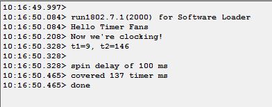
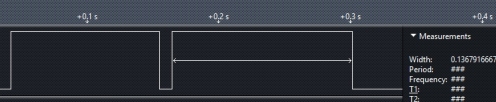
So, the bad news is in that first image where it compares the results of my millis calculation with the spin delay showing a spin delay of 100ms compared to 137ms calculated with millis. The better news is the second image which shoes two things: The actual time is almost bang on the 137ms reported by millis and the spin delay’s 100ms is actuslly 113 ms. Still, that’s an overhead of more than 20% for tracking millis. I can improve that in a few ways:
I Can reduce the resolution to say 10ms; I can reduce the accuracy and accept that a millisecond will be 1.024ms; I can keep the millis value in a register rather than a global memory variable. I think I’ll try reducing the resolution to 2ms and giving up the fractional ms accuracy.
Also: Ahah! I took out the timer stuff and recompiled for the 1802, then re-measured the spin delay with the logic analyzer. A 100ms nominal spin delay took 103ms with the 1802 instruction set. I think the difference is down to reserving registers 0 and 1 making them unavailable for variables.
Yup: Due to an error in the machine description file, reserving regs 0 and 1 left the compiler with only reg 7 for variable and it was going nuts spilling and reloading. I fixed the error(adding regs 4 and 5 to the pool at the same time) and the spin delay went down to almost the nominal value. Interestingly(to me) I had realized a while ago that R6 was always available for variables even though it’s the link register. Both the SCRT and SCAL/SRET always save it before using it.
So, in the end, I may leave things as they are. I bought 20% in performance with the 1806 and if i give that up for better timing, so be it.


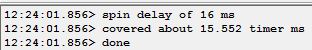
So, my first crack at the 1806 timer functions worked fine. I set the 8 bit counter to a starting value with LDC then put it into timer mode with STM and it counts down one every 32 machine cycles(TPA’s). I get the value with two GEC’s separated by the normal olduino spin delay which just counts instructions and the results are pretty comparable. At 4MHZ the downcount happens every 64US and the range of the counter is a bit more than 16ms. That sounds too short to be useful but I’m actually planning to run it so it interrupts about every millisecond and use an interrupt routine to track milliseconds in a long int and use that for delay() and millis() ala arduino. The code below is all done in C with inline assembler because I’m lazy. the loading and getting of the timer are in functions because that’s the easiest way to get values in and out of assembly routines.
//timer test 1 - 1806 timer counter demo
#include <olduino.h>
#include <nstdlib.h>
#include <cpu1802spd4port7.h>
void LDC(unsigned char c){
	asm(" glo r12 ; pick up the value\n"
		" LDC ;		set the timer\n");
}
unsigned char GEC(){
	asm(" GEC ;		get the value\n"
		" plo r15\n ldi 0\n phi r15 \n"
		" cretn ;	this is the actual return\n");
	return 42;//just to keep the compiler happy
}
void main()
{
	unsigned char t1,t2;
	int i,d=16;
	printf("Hello Timer Fans\n");
	asm(" CID; disable timer interrupts\n");
	LDC(255);//load the timer
	asm(" STM; start the timer\n");
	t1=GEC();
	delay(16);
	t2=GEC();
	printf("t1=%d, t2=%d\n\n",t1,t2);
	printf("spin delay of %d ms\n",d);
	printf("covered about %f timer ms\n",(float)(t1-t2)/(15.625));
	printf("done\n");
}
#include <nstdlib.c>
#include <olduino.c>
I’m now pretty happy with the 1806 proof of concept setup. I have a software loader that I load into low memory using an 1802 processor. The software loader looks like the 1802 in load mode but it writes to memory starting at 0x800 or, if there’s nothing to load, runs the code that’s already there. With the software loader installed i can swap out the 1802 chip for an 1806 and run code that uses the enhanced instruction set.
I’ve got an 1806 target for LCC1802 that compiles C using some of the 1806 enhanced instructions. It gets a modest (20%) performance improvement and frees up a couple of registers.
When I get back to Ottawa I’m going to install an eprom to hold the loader and install the 1806 permanently. I’ll then look at incorporating serial drivers directly in the 1802 and redoing the SPI circuit with a goal of eliminating the AVR completely.
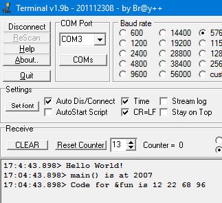
This is the output from the”Hello” program loaded at location 0x800 compiled for the 1802 and then the 1806.

 //fakeloader simulates 1802 load mode in run for 1806
#define nofloats
void main(){
	asm(" 		b4 run\n"			//bypass bootloader if IN pressed
		" 		ldAD 14,0x800\n"	//starting address
		" 		sex 14\n"			//in X register
		"noEF4:	bn4 noEF4\n"		//loop til IN pressed
		"		inp 6\n"			//load memory
		"   	nop\n"
		"		out 7\n"			//and echo
		"yEF4:	b4 yEF4\n"			//wait til switch released
		"		br noEF4\n"			//back for more
		"run:	lbr 0x800\n");	//finally - off we go
}
#include <nstdlib.h>
#include <cpu1802spd4port7.h>
void fun(int i){}

void main()
{
	char* dummy=(void*) &fun;
	printf("Hello World!\n");
	printf("main() is at %x\n",&main);
	printf("Code for a null function starts with %cx\n",dummy[0]);
	if (dummy[0]==0xD5)
		printf("Compiled as an 1802\n");
	else if (dummy[0]==0x68)
		printf("Compiled as an 1806\n");
	else
		printf("I don't know what this is!\n");
}
#include <nstdlib.c>
The 1806 port seems to be working reliably now. Almost all of the adaptation is done in the macros conditioned on setting CPU to 1805 at assembly time (the 1804/5/6 share the enhanced instruction set, 1805 is just what the assembler recognizes). The only changes to the machine description file are to use new epilog/prolog files and to add one to the stack offsets for variables and formal parameters. I could probably fold that back into the macros as well. If I make any backwards compatible improvements to the macros or other code I’ll probably do something like that. As it stands, code created by the new target XR18NW wont work on an 1802.
Rerunning the Dhrystone benchmark, the 1806 clocks 81 Dhrystones/Sec vs 68 on the 1802(both at 4MHZ) an 18% improvement. These compare to over 300 Drhrystones/sec for a Z80 with a much better compiler. The 1806 does 2900 instructions per pass vs 3660 for the 1802 which sounds more impressive but some of the 1806 instructions take longer than the 1802’s which makes up the difference.
So: the changes for the 1806 are:
- adding one to stack offsets for parameters and variables
- using scal/sret for call return
- using RLDI for loading 16 bit constants
- using RLXA and RSXD for 16 bit stack access where practical
- getting rid of places where I inc/dec the stack pointer to make a work area because the stack pointer now points below the last used byte.
- fixing up the odd place where the stack discipline was getting me in trouble – usually to do with calls from one assembly routine to another.
The remaining obvious 1806 instruction is a decrement and branch non-zero(DBNZ) which i will probably incorporate but it’s surprisingly tough to do and probably wouldn’t affect the Dhrystone results at all. All of the 1806 instructions seem more advantageous to someone writing tight code in assembly than for a compiler.
Looking at the generated code reminds me of just how clunky some of it is. I’m tempted to go back and incorporate liveness analysis in my optimizer and have a better look at chaining primitives in the machine description file.
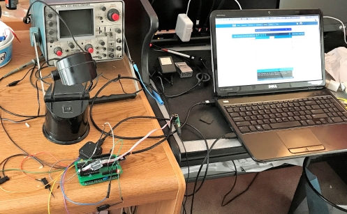
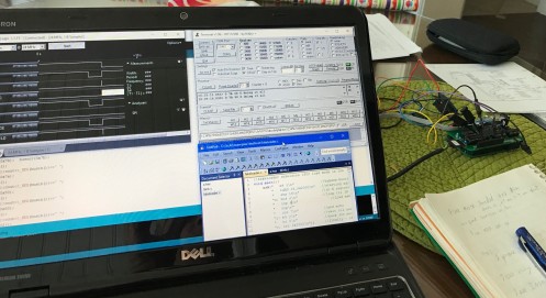
 I am debugging code across four platforms in the most desperate way imaginable
I have a problem with something in my 1806 adaptation corrupting memory and i was trying to use avrdude to read out the memory contents but i now note that somewhere in the evolution of the circuit i started loading the output shift register only on actual I/O from the 1802. I triggers on NAND(N1,TPB) so only when the 1802 has written to port 2,4,6, or 7. In the original circuit I think /LOAD would have been accepted as well as N1. So, back to staring at code.
I fought my way past the stack discipline issue and cleaned up the use of SCAL/SRET and it seems that some aspects of the 1806 do give noticeable speed improvements. I was running the test suite on the latest compiler version and i got a persistent mysterious failure in the float test. The test program just seemed to hang toward the end and stop printing. I assumed something was goobering the stack and going off into lala land but it worked in the emulator and, when I put a blink loop in the compiler cleanup routine it showed that main() was in fact completing.
It seemed to relate to printing a long string and for a while i was imagining something to do with bumping some code over a page boundary but, before getting out the logic analyzer, I stuck some more probe points in and convinced myself that all the code was, in fact executing but the OUT 7’s weren’t driving the AVR to pass them on.
I started to think about timing and did instruction counts relative to baud rate. The AVR is sending data to the host at 57600 baud, 5,760 bytes/second. The 1802/1806 at 4mhz is executing 250,000 instructions/sec so I needed at least 44 instructions between OUT 7’s so the AVR could keep up. Counting instruction times the printstr() routine was using about 58 instructions per character printed and the 1806 cut that down to 40. It wasn’t an issue for most programs but the floating point test prints a single string of 300 bytes and that was enough to blow out the AVR’s buffer.
So: in an actual working program, the 1806 knocks about 30% off the time of an 1802 for the same clock speed!
[Following 14 lines are the inner loop of printstr()]
L22:
;    while(*ptr){
;	putc(*ptr++);
	ldaD R12,7    **1806 RLDI is 2.5 inst vs 4 on 1802
	cpy2 R11,R7   **4
	incm R7,1     **1
	ldn1 R13,R11  **2
	zExt R13      **2
	Ccall _out    **1806 SCAL is 5 inst times vs 17 for 1802
;	}
L23:
	ldn1 R11,R7   **2
	jnzU1 R11,L22 **2.5
;}
[following lines are the body of the OUT routine]
_out:	;raw port output **16 instructions plus Cretn which is 4 on 1806, 10 on 1802
	;stores a small tailored program on the stack and executes it
	dec	sp	;work backwards
	ldi	0xD3	;return instruction
	stxd
	cpy2	rt1,sp	;rt1 will point to the OUT instruction
	glo	regarg1	;get the port number
	ani	0x07	;clean it
	ori	0x60	;make it an out instruction - 60 is harmless
	stxd		;store it for execution
	glo	regarg2	;get the byte to be written
	str	sp	;store it where sp points
	sep	rt1	;execute it
;we will come back to here with sp stepped up by one
+	inc	sp	;need to get rid of the 6x instruction
	inc	sp	;and the D3
	Cretn		;and we're done ** 1806 SRET is 4 inst times vs 10 on 1802
I always want the last word so that wordpress doesn’t eat my code!
So I have the 1806 running reliably and I’ve done a couple of instruction adaptations. So far not so good. My implementation of SCAL/SRET is clumsy and as a result the code is much bulkier. My “Hello From The Other Side” program goes from 5,941 bytes to 6,321. My hope would be that if i get the clumsiness fixed this would come more nearly even. The only other new instruction that looked like an easy win is a 16 bit immediate register load RLDI – that brought me back to 6265 bytes. There are just a couple of other instructions that have potential for performance improvement like register store via X and decrement RSXD and companion RLXA. There are a bunch of decimal instructions which are probably completely useless.
One good thing is that the way i packaged the compiler output as macros really pays off for instruction changes. RLDI, RSXD, and RLXA went into exactly one spot each in the prolog file. The combination of those brought me back to 6161 bytes so, if i started even after SCAL/SRET I’d be down a couple of percent in size and probably a bit better in execution time.
ldiReg:	macro	reg,value
 if MOMCPU=$1805
 	RLDI	reg,value
 else
	ldi	(value)&255
	plo	reg
	ldi	(value)>>8; was/256
	phi	reg
 endif
	endm
popr:	macro	reg
 if MOMCPU=$1805
 	RLXA	reg
 else
	lda	sp
	phi	reg
	lda	sp
	plo 	reg
 endif
	endm
In the image below the 1806 is displaying the four bytes of machine code for the body of a do-nothing function. For the 1802 it would be a single byte D5.
The functional payoff for the 1806 may come from the counter/timer instructions.
It occurred to me that the whole xmodem thing was a waste of time. It’s trivial to have the 1806 fake a load mode like the 1802. All I need is a little program that runs at startup and accepts binary data whenever IN is pressed. Then I can use the existing avrdude on windows and more-or-less the same program in the avr bridge processor. Instead of talking to the 1802 load mode the AVR talks to my fake loader program in the 1802/1806. A piece of cake.
//fakeloader simulates 1802 load mode in run for 1806
void main(){
	asm(" 	b4 run\n"		//bypass bootloader if IN pressed
	" 	ldAD 14,0x2000\n"	//starting address
	" 	sex 14\n"		//in X register
	"noEF4:	bn4 noEF4\n"		//loop til IN pressed
	"yEF4:	b4 yEF4\n"		//wait til switch released
	"	inp 6\n"		//load memory
	"   	nop\n"
	"	out 7\n"		//and echo
	"	br noEF4\n"		//back for more
	"run:	lbr 0x2000\n");	//finally - off we go
}
The 1802/6 loader code really is simple. On startup, it tests EF4 to see if the bootloader should run. Then it loads bytes starting at location 0x2000 every time it sees EF4 go low and then high. To invoke it the AVR resets the 1802/1806 then puts it in run with /EF4 high. It feeds it the code from avrdude then, when that’s done it restarts the 1802/1806 with /EF4 held low to bypass the loader and execute the application at 0x2000.
The changes to the avr loader were simple compared to what was done for xmodem. It looks at the first address avrdude sends for program loading. If it’s 0 it assumes this is an 1802 and it puts it in load mode. If it’s not 0 it puts the assumed 1806 in pseudo-load mode then programs it the same way.
Of course, getting this working involved four programs running on three platforms (avrdude on windows, my loader application on the avr, the fake loader and the loaded application on the 1802/1806). Much head-scratching and logic-analyzer poking was required. But, now that it works it’s all much simpler and once the fake loader is in eprom it should be pretty reliable.
UPDATE: There was a major flaw in my execution of this brilliant idea. By the time the loader starts running we’ve already gone through initialization and we’re running with R3 as program counter. When we branch to the loaded program we run the initialization again and, more specifically, we load R3 again. This does not work well. For some reason it works a lot of the time but future me will spend a couple of days debugging it.
With a couple of false starts I have the 1806 loading and running code and using the 1806 native subroutine call/return instructions.
The 1806 runs pretty well any 1802 code but has a bunch of new instructions including hardware subroutine call/return. It lacks the load mode of the 1802 which is what the AVR uses to bootload it. To get around that I wrote a simple xmodem receiver and loaded it while I had the 1802 chip in the olduino. I then swapped in the 1806 and made the video.
I made a new target for the LCC1802 compiler(XR18NW) that will be the platform for the 1806 adaptation. At the moment it only has my horrible kludge for the subroutine call/return.
//ssxload super simple xmodem loader
//loads a single 32 byte block with checksum from a custom host program
//17-02-08 timeout on initial receives
//17-02-09 no timeouts, single start ack, no error checking
//17-02-09 header read moved into main
//17-02-12 block level error checking and NAK
//17-02-14 send stx before using xmodem. esc is now 0x1b
//17-02-16 slimming down, axloader.h
//17-02-17 target=0x2000, stripping out diagnostic arrays 7621 bytes
#include <nstdlib.h>
#include <olduino.h>
#include <cpu1802spd4port7.h>
#include "xloader.h"
#define blocksize 128
#define target 0x2000
unsigned char *targetdata=(unsigned char *)0x2000; //allows 8K for loader
typedef void (*funptr)();
funptr targetcode=(funptr) target;
unsigned char blkno, hdr,bseq,iseq,ciseq,csum,calcsum,valid;
int readblk(unsigned char * where){//read a block
	unsigned int cnt=blocksize;
	unsigned char ch,rc=0;
	bseq=readch();
	iseq=readch();
	calcsum=0;
	while(cnt>0){
		ch=readch();
		*where++=ch;
		calcsum+=ch;
		cnt--;
	}
	csum=readch(); //read the checksum
	if (calcsum!=csum){//check it
		rc+=4;
	}
	if (bseq!=(blkno+1)){
		rc+=1;
	}
	if (iseq!=(254-blkno)){
		rc+=2;
	}
	return rc;
}

void main(){
	int ch='?',eot=0;
	unsigned char *t=targetdata;
	unsigned int i, tries=0,maxtries=1000;
	unsigned char thishdr;
	blkno=0;
	asm(" seq\n nop\n req\n");
	out(7,STX); //enable interrupts for host data
	putch(NAK); //send NAK to start
	thishdr=readch(); //get the header character

	while(thishdr!=EOT){
		if (SOH==thishdr){
			hdr=thishdr;
			valid=readblk(t);
			if (0==valid){
				blkno++;
				t+=blocksize;
				putch(ACK);
			}else{
				putch(NAK);
			}
		}
		thishdr=getchOrTo(1000);
	}

	putch(ACK);
//and we're done - god willing
	out(7,ETX); //disable interrupts for host data
	//if (++tries<maxtries){
		delay(1000);//let python clear out
		printf("terminating header was 0x%cx\n",thishdr);
		dump(targetdata,16);
		printf("number of blocks %d\n",blkno);
		printf("hh:bn/in c:i r:cs c:cs valid?\n");
		printf("%cx:%cx/%cx c:%cx r:%cx c:%cx %d\n",hdr,bseq,iseq,ciseq,csum,calcsum,valid);
	//}
	printf("\nRun1806(%d)\n",tries);
	asm(" ccall 0x2000\n");
	while(1);
}
#include <nstdlib.c>
#include <olduino.c>
from __future__ import print_function
import sys
import logging
logging.basicConfig()
import serial
try:
    from cStringIO import StringIO
except:
    from StringIO import StringIO
from time import sleep
import os
if len(sys.argv)>1:
    filename=sys.argv[1]
else:
    filename="test32.txt"
print ("File Namee is",filename)
fileSize=os.path.getsize(filename)
print ("File Size is",fileSize)

def xmodem_send(serial, file):
	blocksize=128
	t=0
	#	t, anim ='|/-\\'
	while 1:
	    if serial.read(1) != 'N':
		t = t + 1
		print ('.')
		if t == 3 : return False
	    else:
		break

	p = 1
	s = file.read(blocksize)
	while s:
	    s = s + '\xFF'*(blocksize - len(s))
	    chk = 0
	    for c in s:
		chk+=ord(c)
		#print (c,ord(c),chk,chk%256)
	    while 1:
		serial.write('S') #SOH)
		serial.write(chr(p))
		serial.write(chr(255 - p))
		serial.write(s)
		serial.write(chr(chk%256))
		serial.flush()
		print ('checksum is ',format(chk%256, '02X'),end=' ')
		answer = serial.read(1)
		if  answer == 'N': continue
		if  answer == 'K': break
		print ("unknown answer - length is ",len(answer))
		for character in answer:
  			print (character, character.encode('hex'))
		return False
	    s = file.read(blocksize)
	    p = (p + 1)%256
	    print ('.')
	serial.write('T')
	serial.flush()
	sleep(.1)
	serial.write('T')
	serial.flush()

	return True

#Main program starts here - define the serial port, set RTS off, then open it
#open the file to be loaded
stream = open(filename,'rb')
print("file is open")
port = serial.Serial(parity=serial.PARITY_NONE,
                     bytesize=serial.EIGHTBITS,
                     stopbits=serial.STOPBITS_ONE,timeout=10,xonxoff=0,
                     rtscts=0,dsrdtr=0,baudrate=57600)
port.rts=False
port.port='COM3'
port.open()
port.rts=True
sleep(0.001)
port.rts=False
port.flushInput()
sleep(2) # give avrisp a second to clear out
#transfer the file
result=xmodem_send(port, stream)

stream.close()
port.close()

if result:
    print ("\ntransfer successful")
else:
    print ("\ntransfer unsuccessful")
Final Pro Tip of the day, when you are swapping CPU chips, pay attention to which end goes where!
I first put the 1806 in backwards but it survived the assault.
I noted that the 1806 hardware subroutine call and return operation use the stack a bit differently than my software implementation. A matter of whether you decrement the stack pointer before you store or after. I chose before and they chose after. I remember thinking long and hard about this and deciding my way was better – oh well. It’s essentially arbitrary but because parameters and local variables are stored on the stack, I have to pick one regime and stick to it. As a short term kludge i am attempting to paper over the differences as follows:
- Before each SCAL instruction I decrement the stack pointer so it’s pointing to free memory. On entry to each function i increment the stack pointer to reverse this.
- Before each return I decrement the stack again and after each I increment it (the after case is embedded in the ccall macro).
This is awful but I think it will work in the short term to keep me going. When I get home with the text available I’ll attempt to unwind this and do the right thing: changing my push/pop regime; changing the offsets from the stack pointer for variables and parameters.
;the 1806 SCAL does not decrement SP before pushing the return address
;and the SRET increments it before reloading it
;to accommodate my convention I bracket call/returns with inc/dec as required
;note that the function prolog contains a call to adjspfor1806 which completes the cycle

adjspfor1806: macro	;need to inc the stack to accommodate 1806 - kludge
 if MOMCPU=$1805
 	inc 	2	;leaves sp pointing to last byte of return address
 endif
	endm
Ccall:	macro	target
 if MOMCPU=$1805
 	sex	2
 	dec	2
 	SCAL	6
	dw	target
 	inc	2
 else
	sep	RCALL
	dw	target
 endif
	endm
Cretn:	macro
 if MOMCPU=$1805
 	dec	2
 	sret	6
 else
	sep	RRET
 endif
	endm
I always want the last word so that wordpress doesn’t eat my code!

CDP1806 Standard Call/Return Instructions
The 1802 has no native subroutine call and return operations. For small programs there’s a very quick way of switching program counters that’s arguably better and for more general cases there’s a Standard Call and Return convention(SCRT) that uses registers 4,5 and 6. It’s very well designed though a bit slow and it does tie up 3 registers. The 1806 incorporates two new instructions SCAL(688N) and SRET(689N) that speed up the process and avoids dedicating registers 4,5 and 6 (you still need a register for the return address but it doesn’t have to be 6).
Unfortunately for me the 1806 SCAL/SRET are different from the routines I use in the compiler. They assume that the stack pointer points to the first byte free byte below the stack and can be used freely. The compiler assumes that the stack pointer addresses the last USED byte on the stack and needs to be decremented to point to free memory.
This affects the way parameters and variables are stored and addressed on the stack. One of the parts of LCC that I had the toughest time coming to grips with. I think I could paper over part of them by decrementing SP before each SCAL and incrementing it before each SRET. I would then have to add one to the offset for accessing parameters but variable addressing wouldn’t change. I’ll have to fire up some test cases and try them on an emulator that supports the 1806 instruction set.
For insurance I’ll also make sure that R2 is the X register on each call. It’s an extra instruction but it has saved me from myself in the past.
;Standard Call routine invoked as D4xxxx - big-endian stack convention
	sep     R3 ;go to subroutine
_call	sex	SP ;make sure X=SP
	glo	retAddr ;save previous return pointer on stack
	dec	sp
	stxd
	ghi	retAddr
	str	sp
	glo	RPC ;copy old PC to retAddr
	plo	retAddr
	ghi	RPC
	phi	retAddr
	lda	retAddr ;pick up subroutine address into RPC
	phi	RPC
	lda	retAddr
	plo	RPC
	br	_call-1

;Standard subroutine return
	sep	RPC	;return to the original program
_return	glo	retAddr	;transfer the current return address to RPC
	plo	RPC
	ghi	retAddr
	phi	RPC
	lda	SP	;pick up old return address
	phi	retAddr
	lda	SP
	plo	retAddr
	br	_return-1
Over the last week or so i’ve made a bunch of changes to the AVR code to do with host I/O basically to support the xmodem bootloader but more generally to allow bidirectional serial data.
The external changes are:
- the AVR program can be put in quiet mode by entering ‘p’ quickly after startup, entering ‘q’. Quiet mode eliminates the run1802 message and shortens the startup delay to 1 second
- the AVR recognizes STX in the input stream from the 1802 and enables interrupts so host serial data can be handled properly. ETX disables interrupts so that SPI doesn’t get screwed up.
- The AVR recognizes 0x12 in the input stream as a request to read serial.available(). The AVR puts the value into the input shift register so the 1802 can read it with an INP(6);
- The AVR recognizes 0x00 as a request to read a character from the serial buffer
- The AVR recognizes 0x1B as an escape so that following character is passed on without interpretation.
Additionally, there are a couple of housekeeping changes related to moving to arduino 1.6.5: char1802 is defined unsigned char and output with _BYTE; a #define of MISO was removed because it’s in the standard defines.
ALSO, I increased the size of the input serial buffer from 64 to 256 bytes. I did that by editing
C:\Program Files (x86)\Arduino\hardware\arduino\avr\cores\arduino\HardwareSerial.h and replacing the 64 with 256.
This will get lost when i upgrade the arduino but there doesn’t seem to be a better option for the moment.
//now needs to be compiled with 1.6.5 and the minicore addon.
//ISPV6 meant for use with olduino_2.0_V4E/V8 hardware AND NEW AVRDUDE
//this sketch turns the Arduino into a loader for the 1802 membership card
//adapted from the arduinoisp sketch included with arduino-022
//with credit to David Mellis and Randall Bohen
//July 12 2012 - revamped from aduinoisp1802v8
//mostly pin changes to start
//August 1 - dinking around expanding ? code trying to debug verification failure
//aug 9 changing ! to ~ in interface() ddr settings
//aug 10/11 changed run code to make memrd output and low.
//saved back to olduinoispv2_2
//Aug 16 trying shorter timeout delay (1 sec)
//August 18 trying 57600 baud
//Jan 15, 2014 first build for Olduino V@.0 - all serial/spi
//Jan 26, fixing spi clocking logic in justclock
//Mar 10, 2014 speeding up busout/busin for program loading
//April 3, 2014 moving clock pins to PORTC SCK=PC1, /SCK=PC0, circuit olduino_2.0_v2b.sch
//May 25, 2014 pin definitions changed to match olduino_2.0_v4e schematic
//ldsw,clrsw,datapin=mosi,spiclk,/srclk,srclk,clockbvs
//June 12 speeding up clocking and tightening up timing - 1st try @20mhz
//Aug 10 - increasing presstimeu to 20 us
//aug 10 -presstimeu
//15-01-13 avrdude is requesting version with a 5630 sequence instead of 75'
//17-01-23 experimenting with sending data from host to 1802 program
//         also had to change MISO to MISOX to avoid compile error
//??-??-?? changed char1802 in run1802 to unsigned char cout <<_BYTE(...
//17-02-06 verbose/quites runmode controls run1802 msg
//17-02-14 stx/etx trigger enable/disable interrupts
#define INsw 5 // IN bus pin 27 - normally high
#define presstimeu 20 //us to hold input switch down
#define LDsw 8 // /LOAD(/WAIT) bus pin 29 - arduino PB0 14
#define CLRsw 7 // /CLEAR bus pin 28 - ard pd7 13
#define MEMrd  0 //not connected
//all comm to 1802 is serial.  datapin is connected to the output of MOSR
//MISOX is connected to the input of the 1802's MISR
//sr_sck loads a bit into MISR
//spi_sck tells other devices to grab top bit of MOSR
//notsr_sck advances MOSR and clocks the data in MISR To the storage register
#define datapin 9 //pin to receive shift register data
#define MISOX 12   //output pin hooked to 1802's input shift register
#define MISOPORT PORTB
#define MISODDR DDRB
#define MISOBIT 4  //miso is on port B bit 4
#define sr_sck 15 //pin to clock the data in the shift registers
#define notsr_sck 16 //inverse of sr_sck
#define spi_sck 14 //clock seen at the spi connector.
#define clockport PORTC
#define clockddr DDRC
#define clockbv 3  //both clocks high
#define notclockbv 4 //clocks low, notclock high
#define N0pin 2    //N0 is the 1802 signalling to do host output
#define OUT2pin 6  //signals the 1802 is writing to MOSR
#include <Streaming.h>
#define cout Serial
#define endl '\n'

#define HWVER 2
#define SWMAJ 5
#define SWMIN 0

// STK Definitions
#define STK_OK 0x10
#define STK_FAILED 0x11
#define STK_UNKNOWN 0x12
#define STK_INSYNC 0x14
#define STK_NOSYNC 0x15
#define CRC_EOP 0x20 //ok it is a space...

unsigned long timeoutstart, timeoutinterval=2000; //used to timeout the loader and start the olduino
byte state1802=0;
#define running 1
#define reset 2
#define loading 3
//char runmode; //setting this to 'v' means verbose
char runmode __attribute__ ((section (".noinit")));

void setup() {
  Serial.begin(57600);
  //delay(2000);
  //cout<<"OlduinoII_ISPV6.1 here with runmode="<<runmode<<'\n';
  DDRB=0; //all B pins are inputs (PB5 will have been left as an output by the bootloader)
  digitalWrite(sr_sck,LOW); digitalWrite(spi_sck,LOW);digitalWrite(notsr_sck,HIGH);
  pinMode(sr_sck,OUTPUT); pinMode(notsr_sck,OUTPUT);pinMode(spi_sck,OUTPUT);//set up to drive the shift register
 //doitall();
   //while(1); //loop
  timeoutstart=millis(); //if we don't get anything within timeouttime ms we start the 1802 running
  reset1802();

  //while(1){
  //  justclock();
  //}
}
int error=0;
int pmode=0;
int here; // address for reading and writing, set by 'U' command
uint8_t buff[256]; // global block storage

#define beget16(addr) (*addr * 256 + *(addr+1) )
typedef struct param {
  uint8_t devicecode;
  uint8_t revision;
  uint8_t progtype;
  uint8_t parmode;
  uint8_t polling;
  uint8_t selftimed;
  uint8_t lockbytes;
  uint8_t fusebytes;
  int flashpoll;
  int eeprompoll;
  int pagesize;
  int eepromsize;
  int flashsize;
}
parameter;

parameter param;

void loop(void) {
  uint8_t char1802=0x55;
  if (Serial.available()) {
    avrisp();
    timeoutstart=millis();
  }
  if(millis() - timeoutstart > timeoutinterval){
      run1802(); //run - does not return.
  }
}

uint8_t getch() {
  while(!Serial.available());
  return Serial.read();
}
void readbytes(int n) {
  for (int x = 0; x < n; x++) {
    buff[x] = getch(); //was Serial.read();
  }
}


void empty_reply() {
  char gc=getch();
  if (CRC_EOP == gc) {
    Serial.print((char)STK_INSYNC);
    Serial.print((char)STK_OK);
  }
  else {
    Serial.print((char)STK_NOSYNC);
  }
}

void breply(uint8_t b) {
  if (CRC_EOP == getch()) {
    Serial.print((char)STK_INSYNC);
    Serial.print((char)b);
    Serial.print((char)STK_OK);
  }
  else {
    Serial.print((char)STK_NOSYNC);
  }
}

void get_version(uint8_t c) {
  switch(c) {
  case 0x80:
    breply(HWVER);
    break;
  case 0x81:
    breply(SWMAJ);
    break;
  case 0x82:
    breply(SWMIN);
    break;
  case 0x93:
    breply('S'); // serial programmer
    break;
  default:
    breply(0);
  }
}

void set_parameters() {
  // call this after reading paramter packet into buff[]
  param.devicecode = buff[0];
  param.revision = buff[1];
  param.progtype = buff[2];
  param.parmode = buff[3];
  param.polling = buff[4];
  param.selftimed = buff[5];
  param.lockbytes = buff[6];
  param.fusebytes = buff[7];
  param.flashpoll = buff[8];
  // ignore buff[9] (= buff[8])
  //getch(); // discard second value

  // WARNING: not sure about the byte order of the following
  // following are 16 bits (big endian)
  param.eeprompoll = beget16(&buff[10]);
  param.pagesize = beget16(&buff[12]);
  param.eepromsize = beget16(&buff[14]);

  // 32 bits flashsize (big endian)
  param.flashsize = buff[16] * 0x01000000
    + buff[17] * 0x00010000
    + buff[18] * 0x00000100
    + buff[19];

}

void start_pmode() {
  start_pmode_1802();
  //cout<<"entering program mode";
  pmode = 1;
}

void end_pmode() {
  end_pmode_1802();
  //cout<<"leaving program mode";
  pmode = 0;
}


uint8_t write_flash(int length) {
  write_flash_1802(length);
  return STK_OK;
}

void program_page() {
  char result = (char) STK_FAILED;
  int length = 256 * getch() + getch(); //gets length 1-256
  if (length > 256) {
      Serial.print((char) STK_FAILED);
      return;
  }
  char memtype = getch();
  for (int x = 0; x < length; x++) {
    buff[x] = getch();
  }
  if (CRC_EOP == getch()) {
    Serial.print((char) STK_INSYNC);
    if (memtype == 'F') result = (char)write_flash(length);
    Serial.print(result);
  }
  else {
    Serial.print((char) STK_NOSYNC);
  }
}

void read_signature() {
  if (CRC_EOP != getch()) {
    Serial.print((char) STK_NOSYNC);
    return;
  }
  Serial.print((char) STK_INSYNC);
  #define sig_high 0x1e //dummy (code for part ATMEGA644P
  #define sig_middle 0x96 //device
  #define sig_low 0x0A //signature
  Serial.print((char) sig_high);
  Serial.print((char) sig_middle);
  Serial.print((char) sig_low);
  Serial.print((char) STK_OK);
}
void universal() {//15-01-13 this is being used to retrieve the signature
  int w;
  uint8_t ch;

  for (w = 0; w < 4; w++) { //take the data
    buff[w] = getch();
  }
  if ((buff[0]==0x30)  && (buff[2]==0x00)){
    breply(sig_high);
  }
  else if ((buff[0]==0x30)  && (buff[2]==0x01)){
     breply(sig_middle);
  }
  else if ((buff[0]==0x30)  && (buff[2]==0x02)){
    breply(sig_low);
  }
  else{
    breply(STK_FAILED); //see if this gets a rise out of avrdude
  }
}
//////////////////////////////////////////
//////////////////////////////////////////


void read_page() {
  char result = (char)STK_FAILED;
  int length = 256 * getch() + getch();
  char memtype = getch();
  //cout<<"reading "<<length<<" bytes of "<<memtype<<" ";
  if (CRC_EOP != getch()) {
    Serial.print((char) STK_NOSYNC);
    return;
  }
  Serial.print((char) STK_INSYNC);
  if (memtype == 'F') result = read_page_1802(length);
  Serial.print(result);
  return;
}

////////////////////////////////////
////////////////////////////////////
I always want the last word so that wordpress doesn’t eat my code!
int avrisp() {
  uint8_t data, low, high, gc;
  uint8_t ch =getch();    //cout<<"<"<<_HEX(ch)<<" ";
  switch (ch) {
  case '?': //debug
    doitall();
    break;
  case 'v': //verbose mode
    runmode='v';
    break;
  case 'q': //quiet mode
    runmode='q';
    cout<<"going silent\n";
    break;
  case '!': //run
    cout<<"!=runq\n";
    runmode='q';
    run1802();
    break;
  case '0': // signon
    empty_reply();
    break;
  case '1':
    gc=getch(); //cout<<":"<<_HEX(gc)<<" ";
    if (gc == CRC_EOP) {
      Serial.print((char) STK_INSYNC);
      Serial.print("AVR ISP");
      Serial.print((char) STK_OK);
    }
    break;
  case 'A':
    gc=getch(); //cout<<":"<<_HEX(gc)<<" ";
    get_version(gc);
    break;
  case 'B':
    readbytes(20);
    set_parameters();
    empty_reply();
    break;
  case 'E': // extended parameters - ignore for now
    readbytes(5);
    empty_reply();
    break;

  case 'P':
    start_pmode();
    empty_reply();
    break;
  case 'U':
    here = getch() + 256 * getch();
    sethere_1802();
    //cout<<"here="<<_HEX(here);
    empty_reply();
    break;

  case 0x60: //STK_PROG_FLASH
    low = getch();
    high = getch();
    empty_reply();
    break;
  case 0x61: //STK_PROG_DATA
    data = getch();
    empty_reply();
    break;

  case 0x64: //STK_PROG_PAGE
    program_page();
    break;

  case 0x74: //STK_READ_PAGE
    read_page();
    break;

  case 'V':
    universal();
    break;
  case 'Q':
    error=0;
    end_pmode();
    empty_reply();
    //run1802();
    break;

  case 0x75: //STK_READ_SIGN
    read_signature();
    break;

  // expecting a command, not CRC_EOP
  // this is how we can get back in sync
  case CRC_EOP:
    Serial.print((char) STK_NOSYNC);
    break;

  // anything else we will return STK_UNKNOWN
  default:
    if (CRC_EOP == getch())
      Serial.print((char)STK_UNKNOWN);
    else
      Serial.print((char)STK_NOSYNC);
  }
}
I always want the last word so that wordpress doesn’t eat my code!
#define sbi(sfr,bit) (_SFR_BYTE(sfr) |= _BV(bit))
#define cbi(sfr,bit) (_SFR_BYTE(sfr) &= ~_BV(bit))
void busout(uint8_t t){ //put a byte on the bus
  sbi(MISODDR,MISOBIT);
  for (int i=0;i<8;i++){
      if(MISOX, t&0x80){
        sbi(MISOPORT,MISOBIT);
      }else{
        cbi(MISOPORT,MISOBIT);
      }
      clockport=clockbv;//clock up, notclock down
      asm("  nop\n");
      clockport=notclockbv;//clock down, notclock up
      t<<=1;
  }
  cbi(MISODDR,MISOBIT);
}
uint8_t busin(){ //read a byte from the 1802
  uint8_t buschar;
//bit 7 of the byte is already in position to be read, the others have to be clocked in
  buschar=0; //clear the character
  for (uint8_t i = 0; i < 8; ++i) {  //get the 8 bits in sequence
	buschar = (buschar<<1)|digitalRead(datapin); //read bits 0-7 in sequence ad set them in the byte
      clockport=clockbv;//clock up, notclock down
      asm("  nop\n");
      clockport=notclockbv;//clock down, notclock up
  }
  return buschar;
}
void justclock(){ //just run the spi clock
      clockport=clockbv;//clock up, notclock down
      clockport=notclockbv;//clock down, notclock up
      asm("nop\n");
      clockport=clockbv;//clock up, notclock down
      asm("nop\n");
      clockport=notclockbv;//clock down, notclock up
      asm("nop\n");
      clockport=clockbv;//clock up, notclock down
      asm("nop\n");
      clockport=notclockbv;//clock down, notclock up
      asm("nop\n");
      clockport=clockbv;//clock up, notclock down
      asm("nop\n");
      clockport=notclockbv;//clock down, notclock up
      asm("nop\n");
      clockport=clockbv;//clock up, notclock down
      asm("nop\n");
      clockport=notclockbv;//clock down, notclock up
      asm("nop\n");
      clockport=clockbv;//clock up, notclock down
      asm("nop\n");
      clockport=notclockbv;//clock down, notclock up
      asm("nop\n");
      clockport=clockbv;//clock up, notclock down
      asm("nop\n");
      clockport=notclockbv;//clock down, notclock up
      asm("nop\n");
      clockport=clockbv;//clock up, notclock down
      asm("nop\n");
      clockport=notclockbv;//clock down, notclock up
}
void run1802(){
  unsigned char char1802=21, pindsave,escmode=false; //char from 1802, captured PIND;
  if ('v'==runmode){
    cout<<" run1802.6.1("<<timeoutinterval<<")"<<"\n";
  }
  //Serial.end(); Serial.begin(9600);
  interface(INPUT); //release the pins(really just INsw)
  digitalWrite(CLRsw,LOW);   digitalWrite(LDsw,LOW);//ensure wait state
  delay(5);
  digitalWrite(LDsw,HIGH); //reset
  delay(5);
  pinMode(MEMrd,OUTPUT); digitalWrite(MEMrd,LOW); //AUG 10 -make sure 1802 can write
  digitalWrite(CLRsw,HIGH); //run
  state1802=running;
  cbi(TIMSK0,TOIE0);
  noInterrupts(); //default is no interrupts
  while(true){ //loop for 1802 program output
    while (PIND&0x40); //wait for SPI signal to go low
    pindsave=PIND; //grab the n0 line while it's valid
    while (0==(PIND&0x40)); //wait for trailing edge - signal goes high again
    if (pindsave&0x04){ //if it's for me  ** have to test this now
      char1802=busin(); //grab the character and clock the SPI bus
      if (escmode==1){//escaping this character
        cout<<_BYTE(char1802); //send it to the host
        escmode=0;
      }else{
        switch(char1802){
          case 0x12: //querying for avail characters
            busout(Serial.available());
            break;
          case 0: //wanting host characters
            busout(getch());
            break;
          case 0x1b: //escape next character
            escmode=1;
            break;
          case 0x02: // allow interrupts
            interrupts(); break;
          case 0x03: // disallow interrupts
            noInterrupts(); break;
          default:
            cout<<_BYTE(char1802); //send it to the host
        }
      }
   } else{ //not for me, have to do this fast
      justclock(); //just clock the SPI bus
    }
  }
}
void domeall(){
 }

void doitall(){
  uint8_t c18;
  cout<<"doing it all\n";
  interface(OUTPUT);
   //start the write sequence
  reset1802();
  digitalWrite(LDsw,LOW);  //then go to load mode
 // busout(0xaa);
  //while(1);
  busout(0x7b);
  pressin();
  busout(0x7a);
  pressin();
  busout(0x7a);
  pressin();
  busout(0x7a);
  pressin();
  busout(0x7a);
  pressin();
  busout(0x30);
  pressin();
  busout(0x00);
  pressin();
  reset1802();
  run1802();
while(1);
}
void sethere_1802(){
  if (here==0){ //if it wants to read from the beginning, fine
    reset1802();
    digitalWrite(LDsw,LOW);  //then go to load mode
  } //otherwise ignore it
}
void start_pmode_1802() {
  interface(OUTPUT); //set rquired pins to OUTPUT
  reset1802();
  digitalWrite(LDsw,LOW);  //then go to load mode
  //cout<<"entering program mode";
  pmode = 1;
}

void end_pmode_1802() {
  //cout<<"leaving program mode";
  pmode = 0;
}
void pressin(){
  digitalWrite(INsw,LOW); //toggle
  delayMicroseconds(presstimeu);
  digitalWrite(INsw,HIGH);
  delayMicroseconds(presstimeu);
}
void reset1802(){
  pinMode(CLRsw,OUTPUT); pinMode(LDsw,OUTPUT);
  digitalWrite(CLRsw,LOW);   digitalWrite(LDsw,LOW);//reset
  digitalWrite(LDsw,HIGH); //1802
  state1802=reset;
}

void interface(uint8_t io){ //setting pins to INPUT or OUTPUT
 //really need to rethink this
  digitalWrite(MISOX,LOW);
  digitalWrite(INsw,HIGH);
  digitalWrite(spi_sck,LOW);digitalWrite(sr_sck,LOW);digitalWrite(notsr_sck,HIGH);
  digitalWrite(LDsw,LOW);digitalWrite(CLRsw,LOW);
  pinMode(MISOX,INPUT);//MISO is controlled by busout
  pinMode(spi_sck,OUTPUT);pinMode(sr_sck,OUTPUT);pinMode(notsr_sck,OUTPUT); //clocks are always output
  pinMode(CLRsw,OUTPUT);pinMode(LDsw,OUTPUT);  //ld & clr are always output
  pinMode(INsw,io);  //in controlled here
}


uint8_t read_byte_1802() {//first try
  digitalWrite(INsw,LOW);//push input button
  delayMicroseconds(presstimeu);
  digitalWrite(INsw,HIGH);
  delayMicroseconds(presstimeu);
  uint8_t buschar=busin();
  return buschar;
}
char read_page_1802(int length) {//first try
  digitalWrite(MEMrd,HIGH); //make sure we're read only
  for (int x = 0; x < length; x+=1) {
    Serial.print((char) read_byte_1802());
  }
  return STK_OK;
}

uint8_t write_flash_1802(int length) {
  int x = 0;
  digitalWrite(MEMrd,LOW); //allow memory write
  while (x < length) {
    write_byte_1802(buff[x++]); //we can only write bytes sequentially from address 0
  }
  digitalWrite(MEMrd,HIGH); //make sure we're read only
  return STK_OK;
}

void write_byte_1802(char data){ //write a byte to the 1802
  busout(data); //put it on the data bus
  digitalWrite(INsw,LOW);//push input button
  delayMicroseconds(presstimeu);
  digitalWrite(INsw,HIGH);
  delayMicroseconds(presstimeu);
}
I always want the last word so that wordpress doesn’t eat my code!
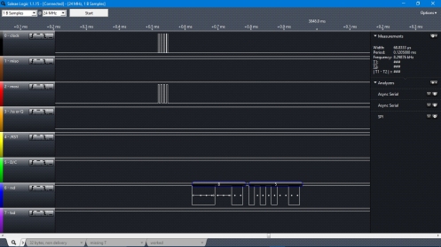
After getting the revised serial bridge code in the AVR working with a new version(olduinoII_ISPV6) I figured I should make sure it was backward compatible with the VF5 that I had been using. It didn’t work with the little nokia lcd so i decided to reload VF5 in the AVR to make sure it wasn’t an LCD hardware problem. Of course, VF5 doesn’t work! Running a simple program that sends an ASCII ‘U'(0x55) from the 1802 I get it sending 0x38 0x35 to windows. The AVR program itself sends text fine but when it’s bridging for the 1802 it Fs it up.
Ahh, I think I know. The character is being held in a uint8_t and the streaming output thingy is converting it so ‘U'(0x55) is coming out as its decimal equivalent 85. What a waste of time! I see that in V6 I had declared it unsigned char and the output line was cout<<_BYTE(char1802); so i must have solved this a while ago and forgotten. Dummy.
